
Contact information
Free service hotline
net04@gtggroup.com
TEL: 0769-85075888-6618
13925591357
Fax: 0769-85075898
Mail: net04@gtggroup.com
ADD: Huacan Industrial Park, No. 2 Keji 8th Road, Songshan Lake Park, Dongguan City, Guangdong Province
UPS Battery Backup FCC Certification Testing Standards and Compliance
FCC Part 15 Subpart B certification is a mandatory electromagnetic compatibility requirement for uninterruptible power supply systems entering the United States market. As unintentional radiators, UPS devices must demonstrate compliance with conducted and radiated emission limits measured in accordance with ANSI C63.4. This article provides a detailed technical examination of the FCC Part 15B regulatory framework, device classification methodology, core test parameters, laboratory setup requirements, and practical strategies for achieving first-pass certification success — focused on the needs of power electronics design engineers and compliance managers.
FCC Part 15B Regulatory Framework for UPS Systems
FCC Part 15 (47 CFR Part 15) establishes the technical standards and administrative requirements for radio frequency devices marketed in the United States. UPS systems fall under Subpart B — Unintentional Radiators — which covers devices that generate radio frequency energy during operation but do not intentionally emit RF signals. The applicable rule sections are 15.107 (conducted emission limits) and 15.109 (radiated emission limits), with measurement procedures defined in ANSI C63.4.
Class A vs. Class B Classification for UPS Equipment
The FCC Part 15B classification determines emission limit stringency and has direct consequences for device labeling, user documentation, and market access. UPS products are categorized as follows:
- Class A — Equipment marketed for use in commercial, industrial, or business environments. This classification typically applies to data center UPS systems, telecom-grade UPS equipment, and industrial UPS units with ratings above 3 kVA. Class A conducted emission limits range from 56 to 60 dBμV quasi-peak (frequency-dependent) and radiated emission limits at 10 meters range from 39 to 49.5 dBμV/m.
- Class B — Equipment marketed for use in residential environments. Applies to desktop UPS units, home office UPS systems, and consumer-grade backup power products typically rated below 1.5 kVA. Class B limits are approximately 10 dB more stringent than Class A, imposing significantly tighter design constraints on conducted and radiated emissions.
The classification decision must be made at the product definition stage and documented in the compliance file. A product designed to Class A limits cannot be later marketed as Class B-compliant without retesting. Conversely, a Class B-compliant UPS may be marketed for both residential and commercial applications. For UPS systems that incorporate display panels, network interfaces, or monitoring ports, these peripheral functions are included in the overall device classification — they do not trigger separate FCC rule parts unless they incorporate radio transmitters.
SDOC Compliance Path for UPS Equipment
UPS systems follow the Supplier's Declaration of Conformity (SDOC) procedure under FCC Part 2 Subpart J. The SDOC path requires: testing at an FCC-recognized accredited laboratory; preparation of a compliance information statement; product labeling with FCC compliance information; and retention of test records. Unlike the certification procedure (which requires FCC ID issuance), SDOC does not involve filing with the FCC or obtaining a grant of equipment authorization. However, the responsible party — typically the manufacturer or US-based importer — must maintain complete technical documentation and be prepared to produce it upon request by the FCC within a reasonable timeframe.
Important note: UPS systems that include wireless communication modules — such as Wi-Fi for SNMP-based remote monitoring, Bluetooth for local configuration, or cellular modems for cloud connectivity — trigger additional requirements under FCC Part 15 Subpart C (Intentional Radiators). Each radio transmitter must obtain a separate FCC ID certification. The base UPS unit remains under SDOC for Part 15B, but the composite product must satisfy both compliance paths. Manufacturers should conduct a complete RF function inventory early in the design phase to avoid last-minute certification surprises.
Conducted and Radiated Emission Testing — Technical Deep Dive
FCC Part 15B emission testing for UPS systems involves two fundamental measurement categories. Each presents distinct technical challenges that design engineers must understand to interpret test results effectively and implement targeted corrective measures.
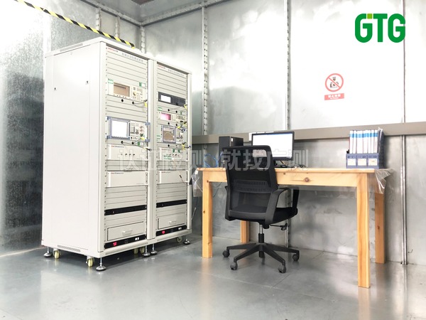
Conducted Emissions — 150 kHz to 30 MHz
Conducted emission measurements quantify the radio frequency noise that a UPS injects back into the AC mains supply through its power cord. A Line Impedance Stabilization Network is inserted between the AC mains and the Equipment Under Test, providing a defined impedance and a measurement port for the EMI receiver. Both line and neutral conductors are measured independently, with quasi-peak and average detectors applied at each frequency.
UPS conducted emission challenges are concentrated in three frequency regions: below 2 MHz — dominated by differential-mode noise from the power factor correction stage and primary-side switching; 2 MHz to 10 MHz — a transition region where both differential-mode and common-mode noise mechanisms contribute; and 10 MHz to 30 MHz — primarily common-mode noise coupled through parasitic capacitances in transformers and heat sinks. Effective EMI filter design must address each region with appropriate filtering topologies: X-capacitors and differential-mode chokes for the low-frequency region, Y-capacitors and common-mode chokes for the high-frequency region, and a combination for the transition region.
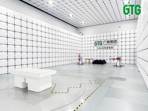
Radiated Emissions — 30 MHz to 1 GHz (and Beyond)
Radiated emission testing measures the electromagnetic field strength emitted from the UPS enclosure, cables, and connected peripherals. Testing is performed in a semi-anechoic chamber or on an open-area test site, with the receiving antenna positioned at the specified measurement distance — typically 10 meters for Class A and 3 meters for Class B. The EUT is rotated through 360 degrees on a turntable, and the antenna height is scanned from 1 to 4 meters to capture the maximum emission at each frequency.
For UPS systems, the dominant radiated emission sources are typically: the power switching devices and their associated heat sinks, which act as unintentional antennas; output cables carrying high-frequency ripple currents; and ventilation openings that compromise enclosure shielding effectiveness. The switching frequency harmonics — often spanning from tens of megahertz to several hundred megahertz — are the primary emission contributors. Design-stage mitigation strategies include optimizing the power loop layout to minimize loop area, adding ferrite suppression cores on internal and external cables, improving chassis grounding continuity, and designing ventilation openings with dimensions below a quarter-wavelength of the highest offending frequency.
Test Operating Modes — Mains Mode vs. Battery Mode
A critical but often overlooked aspect of UPS emission testing is the requirement to evaluate both operating modes. In mains mode, the UPS rectifier and inverter are active, with EMI filter components in the AC input path contributing to conducted emission suppression. In battery mode, the AC input path is disconnected, removing the EMI filter from the noise path — this can result in higher conducted emissions on the output side. Both modes must be tested at representative load conditions, typically 50% to 80% of rated output power. The test report must clearly document the operating mode, load configuration, and any auxiliary equipment connected during testing to ensure reproducibility and traceability.
EMC Design Strategies for First-Pass FCC Certification Success
Achieving first-pass compliance in FCC Part 15B testing requires proactive EMC design integration throughout the product development lifecycle. The following engineering practices represent proven approaches for UPS design teams.
PCB-Level EMI Control for Power Electronics
The PCB layout of the UPS power stage is the single most influential factor in conducted and radiated emission performance. Critical design rules include: minimizing the high-frequency switching loop area formed by the power switch, transformer primary winding, and input bulk capacitor; implementing a single-point grounding architecture that separates power ground, signal ground, and chassis ground, with controlled interconnection impedance; placing the input EMI filter physically adjacent to the AC inlet connector to prevent noise coupling onto unfiltered traces; and routing sensitive signal traces away from high-dv/dt nodes such as switching transistor drains and transformer secondary-side rectifier anodes. Multi-layer PCB designs with dedicated ground planes significantly outperform two-layer designs for EMC control in power conversion applications above 500 W.
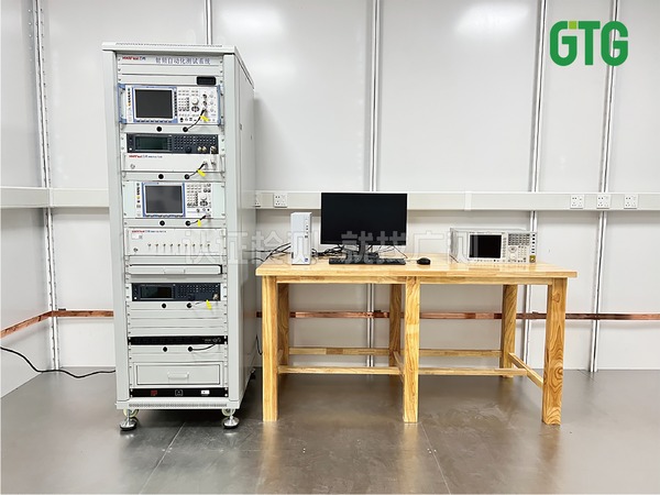
Pre-Compliance Testing as a Risk Reduction Tool
Pre-compliance EMC testing — conducted in-house or at a test laboratory using simplified setups — is a practical methodology for identifying emission problems before formal certification. A basic pre-compliance setup can include a spectrum analyzer with quasi-peak detection capability, a LISN for conducted emission measurements, and a near-field probe set for identifying emission hot spots on the PCB and cabling. While pre-compliance measurements do not substitute for formal testing at an FCC-recognized laboratory, they provide rapid feedback during the development cycle and can prevent costly formal test failures. Key pre-compliance test points include: conducted emission scan on the AC input with the UPS in both mains mode and battery mode; near-field probing of the main power transformer, PFC inductor, and switching transistors; and radiated emission pre-scan in an in-house shielded enclosure or at reduced measurement distance.
Cross-Certification Synergies — FCC, CE, and International EMC Standards
UPS products destined for global markets face a matrix of EMC requirements: FCC Part 15B (United States), EN 55032 / EN 55011 (European Union), ICES-003 (Canada), AS/NZS CISPR 32 (Australia/New Zealand), and various national derivatives. The measurement methodologies share common roots in CISPR standards, and the test frequency ranges substantially overlap. A well-planned certification campaign can leverage a single chamber session to capture data for multiple standards simultaneously. For example, conducted emission measurements from 150 kHz to 30 MHz per CISPR 32 satisfy EN 55032, CISPR 32, and AS/NZS CISPR 32 requirements directly, and can be reviewed against FCC Part 15B limits with minor conversion. This integrated approach to multi-standard testing maximizes laboratory utilization and reduces total certification cycle time.
Frequently Asked Questions
Q1 How does FCC Part 15B differ from Part 15 Subpart C for UPS products?
Part 15 Subpart B governs unintentional radiators — devices like UPS systems that generate RF energy as a byproduct of operation. Part 15 Subpart C governs intentional radiators — devices that deliberately emit RF signals, such as Wi-Fi and Bluetooth modules. A standalone UPS without wireless functionality falls exclusively under Subpart B. If the UPS incorporates a wireless module for remote monitoring or configuration, that module must comply with Subpart C (requiring FCC ID certification), while the base UPS remains under Subpart B SDOC.
Q2 What is the measurement distance difference between Class A and Class B radiated emission testing?
Class A equipment is measured at a 10-meter distance, while Class B is typically measured at 3 meters. This difference reflects the distinct usage environments — Class A devices operate in larger commercial/industrial spaces where a 10-meter measurement is more representative, while Class B devices in residential settings have closer proximity to other electronic equipment, hence the 3-meter measurement. The limit values are adjusted accordingly, and direct numerical comparison between the two classes requires distance scaling using the 20 dB/decade extrapolation factor per ANSI C63.4.
Q3 Do online double-conversion UPS and line-interactive UPS have different FCC testing requirements?
FCC Part 15B does not differentiate between UPS topologies — the same emission limits and measurement procedures apply regardless of whether the unit is online double-conversion, line-interactive, or standby (offline). However, the EMI characteristics differ significantly by topology. Online double-conversion UPS systems have the inverter operating continuously, producing a relatively steady-state emission profile. Line-interactive and standby UPS units may have a more benign emission profile in mains mode (when the inverter is idle or in bypass) but exhibit a step change in emissions when transitioning to battery mode. This behavior must be captured in the test plan by ensuring all operating modes are measured.
Q4 When does a UPS design change require FCC recertification?
Under the SDOC framework, there is no formal FCC notification requirement for design changes — the responsibility rests with the manufacturer to determine whether continued compliance is maintained. Changes that typically warrant retesting include: replacement of the main switching power semiconductors with devices having different switching characteristics; modification of the PCB layout affecting the power stage, EMI filter, or grounding scheme; changes to the enclosure design that affect shielding effectiveness; addition of new internal clock sources or communication interfaces; and changes to the EMI filter component values or topology. A documented engineering change assessment process should be in place to evaluate the EMC impact of each design revision.
Q5 Can UPS FCC testing performed for the US market be reused for Canadian ISED compliance?
To a significant extent, yes. Canada's ISED ICES-003 standard for unintentional radiators is closely harmonized with FCC Part 15B, referencing ANSI C63.4 for measurement procedures and adopting substantially equivalent emission limits. Test data generated for FCC Part 15B compliance can generally support ICES-003 compliance claims, subject to verification that the measurement setup and operating conditions satisfy both sets of requirements. The key difference is administrative: ICES-003 requires a Canadian representative for imported products, and the compliance labeling requirements differ from FCC requirements. Planning combined FCC and ISED testing from the outset avoids duplication of chamber time and reduces overall certification cost.
This content is provided for industry communication and informational reference only and does not constitute any form of certification commitment, testing advice, or legal opinion. The certification requirements, procedures, and standards referenced herein may change as regulations evolve — please refer to the latest official announcements from the relevant authorities. Specific certification requirements, timelines, and costs must be evaluated by professional engineers based on the actual product. For inquiries, please contact us by phone.
Phone: +86 13925591357 | Email: net04@gtggroup.com | www.gtggroup.cn