
Contact information
Free service hotline
net04@gtggroup.com
TEL: 0769-85075888-6618
13925591357
Fax: 0769-85075898
Mail: net04@gtggroup.com
ADD: Huacan Industrial Park, No. 2 Keji 8th Road, Songshan Lake Park, Dongguan City, Guangdong Province
Inverter FCC Certification Guide for US Market Entry
Exporting inverters to the United States requires compliance with Federal Communications Commission (FCC) regulations, a legal prerequisite that can determine whether your product reaches the market at all. For technical teams navigating this process for the first time, the regulatory landscape can appear complex and unforgiving. This practical guide walks you through the essential requirements of FCC certification for inverters, covering key EMC test items, common design pitfalls that cause failures, and strategies for selecting a qualified testing partner. Whether you are developing a new product line or entering the US market for the first time, understanding these requirements early in your design cycle can save significant time and resources. Partnering with an experienced testing laboratory is critical to achieving compliance efficiently.
Understanding the FCC Regulatory Framework for Inverters
The FCC regulates electromagnetic emissions from electronic devices sold in the United States under Title 47 of the Code of Federal Regulations (CFR). For inverter manufacturers, the most relevant regulation is FCC Part 15, which governs unintentional radiators — devices that generate radio frequency energy as a byproduct of their operation rather than by design. Since all inverters use high-frequency switching circuits for power conversion, they inherently produce electromagnetic emissions that must be controlled.
FCC Part 15 Classification: Class A vs. Class B
FCC Part 15 divides unintentional radiators into two categories based on their intended operating environment. Class A applies to devices designed for use in commercial, industrial, or business environments. Class B applies to devices intended for use in residential environments, and imposes stricter emission limits. The classification your inverter falls under directly determines the emission thresholds you must meet during testing.
- Commercial/industrial inverters — typically classified as Class A, with higher permissible emission limits
- Residential solar inverters and home energy storage systems — classified as Class B, with significantly lower emission limits
- Hybrid inverters with wireless features — may require both Part 15 unintentional radiator testing and separate Part 15 intentional radiator certification for the radio module
Pro Tip: If your inverter includes Wi-Fi, Bluetooth, Zigbee, or any other wireless communication module, you must verify whether the radio module itself holds a valid FCC ID. Using a pre-certified radio module can simplify your overall certification process significantly.
The FCC Certification Process Overview
The FCC certification process for inverters generally follows a structured pathway. First, you determine the applicable FCC part and classification for your product. Then, you prepare a representative sample and submit it to an accredited testing laboratory for evaluation. After testing, the results are compiled into a test report, which is submitted to a Telecommunication Certification Body (TCB) for review. Upon approval, your product receives an FCC ID, which must be displayed on the device and its packaging. The entire workflow demands careful planning, particularly regarding sample preparation and documentation.
Key EMC Test Items for Inverter FCC Certification
FCC certification for inverters centers on electromagnetic compatibility (EMC) testing. The goal is to verify that your inverter does not emit excessive electromagnetic interference (EMI) that could disrupt other electronic devices, radio communications, or telecommunications equipment. Below are the core test items you should expect during the certification process.
Conducted Emissions Testing
Conducted emissions testing measures the electromagnetic noise that your inverter sends back through its AC power cord into the electrical mains. This test typically covers the frequency range from 150 kHz to 30 MHz. Inverters are particularly prone to conducted emissions because their switching power supplies generate high-frequency noise on both the input and output power lines. The limits for Class B devices are more stringent than Class A, making residential inverters more challenging to pass.
Radiated Emissions Testing
Radiated emissions testing measures the electromagnetic energy that your inverter emits into the surrounding space through the air. This test covers a broad frequency range, typically from 30 MHz up to several GHz, depending on the highest internal clock frequency in the device. For high-power inverters, radiated emissions are often the most difficult test to pass. The switching transistors, bus bars, and internal cabling can all act as unintentional antennas, broadcasting electromagnetic noise at levels that exceed permissible limits.
Immunity Testing Considerations
While FCC Part 15 primarily focuses on emission limits, understanding immunity performance is equally important for product reliability. Tests such as electrostatic discharge (ESD), radiated immunity, and electrical fast transient (EFT) / burst immunity help ensure that your inverter operates reliably in real-world electromagnetic environments. Although these tests are not always mandatory under FCC Part 15, they are commonly required under other standards that your product may need to meet simultaneously, such as those specified by UL or other North American safety standards.
Harmonic Current Emissions
For grid-tied inverters, harmonic current emissions on the AC output side represent another critical compliance area. The rapid switching of power semiconductor devices can introduce current harmonics into the utility grid, potentially affecting power quality for other users. While harmonic testing falls under different standards than FCC Part 15, it is an essential part of the overall compliance picture for inverters connecting to the US grid.
Common Design Pitfalls That Cause FCC Test Failures
Many inverter manufacturers encounter unexpected failures during FCC testing, often resulting in costly redesigns and project delays. Understanding the most common technical causes of failure can help your engineering team address potential issues during the design phase rather than after submitting samples for testing.
Switching Noise and EMI Filter Design
The power conversion circuits inside an inverter rely on rapid switching of MOSFETs or IGBTs operating at frequencies that can generate significant electromagnetic noise. Poorly designed EMI filters on the input and output sides of the inverter are the single most common cause of FCC test failures. The filter must be designed to attenuate noise across the entire frequency range covered by the applicable emission limits, not just at the fundamental switching frequency. Many designs focus on filtering at the primary switching frequency while neglecting harmonics and broadband noise at higher frequencies.
PCB Layout and Grounding Issues
Printed circuit board (PCB) layout plays a critical role in controlling electromagnetic emissions. Common mistakes include inadequate separation between high-power switching circuits and sensitive control circuits, poor grounding strategies that create ground loops, and routing high-current traces in ways that create large loop areas acting as magnetic field antennas. A well-designed PCB with proper grounding, minimized loop areas, and strategic placement of decoupling capacitors can dramatically reduce emissions before any filter components are even applied.
- Large current loops — create strong magnetic field emissions that are difficult to filter after the fact
- Shared ground paths — allow switching noise to couple into control and communication circuits
- Insufficient copper pour — reduces the effectiveness of the ground plane as a shield for emissions
Cable and Connector Emissions
External cables connected to an inverter — including DC input cables, AC output cables, communication cables, and sensor cables — can act as highly efficient antennas for electromagnetic noise. The RF currents flowing on these cables are often the dominant source of radiated emissions during testing. Proper use of ferrite cores, shielded cables, and filtered connectors can significantly reduce cable-borne emissions. However, these solutions must be integrated into the design from the beginning, as adding shielding or filtering after a test failure may require mechanical redesign.
Pro Tip: Always prepare your test samples with the longest cables specified in your product configuration. Longer cables produce higher radiated emissions, and testing with short cables may yield passing results that do not reflect real-world performance.
Selecting the Right Testing Laboratory for Inverter Certification
Choosing the right testing laboratory is a strategic decision that can significantly impact your certification timeline and overall project cost. Not all laboratories have the equipment, expertise, or capacity to handle high-power inverter testing effectively. The following factors should guide your selection process.
Accreditation and Recognition
Verify that the laboratory holds ISO/IEC 17025 accreditation for the specific test methods required by FCC Part 15. Accreditation ensures that the laboratory operates under a quality management system that produces reliable and reproducible test results. Additionally, check whether the laboratory is recognized by the FCC or accredited by a recognized accreditation body such as A2LA or NVLAP. Test reports from non-accredited laboratories may not be accepted by Telecommunication Certification Bodies (TCBs), potentially requiring you to retest at an accredited facility.
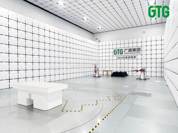
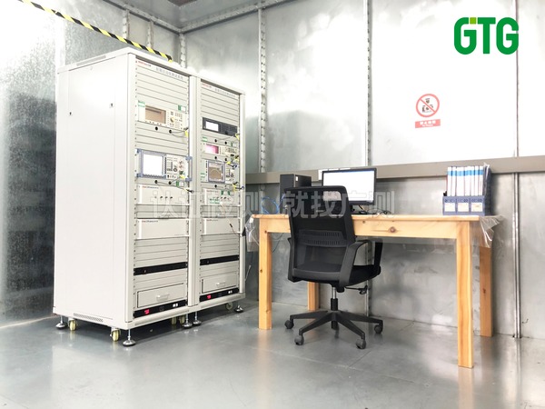
Technical Capability for High-Power Devices
Inverters present unique testing challenges due to their high power levels, large physical dimensions, and significant heat generation during operation. The laboratory must have the infrastructure to support these requirements, including sufficiently large semi-anechoic chambers or open area test sites (OATS), appropriate power supply equipment capable of handling the inverter's rated power, and proper ventilation or cooling systems to maintain stable operating conditions during extended test sequences.
Engineering Support and Pre-Compliance Services
A testing laboratory that offers engineering support alongside formal testing can provide tremendous value, especially for teams new to FCC certification. Pre-compliance testing allows you to identify and address emission issues before committing to the formal certification test, reducing the risk of expensive failures. Look for laboratories whose engineers can provide practical design recommendations based on test results, helping your team understand the root cause of any failures and develop effective mitigation strategies.
Pro Tip: Consider engaging your testing laboratory during the design review stage, before your PCB layout is finalized. Early consultation on EMC design practices can prevent the most common and costly failure modes.
A reliable testing and certification partner with deep experience in power electronics and inverter testing can guide your team through the entire certification journey, from initial design consultation through final report delivery.
Documentation and Labeling Requirements for FCC Compliance
Beyond passing the technical EMC tests, FCC certification requires careful attention to documentation and product labeling. Errors or omissions in these areas can delay certification approval or create compliance issues during market surveillance.
Required Documentation Package
The documentation package submitted to the TCB typically includes the complete test report from the accredited laboratory, block diagrams and schematics of the device, a description of the device's function and operating modes, photographs of the device (internal and external), the user manual with required FCC compliance statements, and details of any modifications made during or after testing. Each document must be consistent with the others — discrepancies between the schematics, photographs, and test configuration are a common source of delays during TCB review.
FCC ID and Labeling Requirements
Once certification is granted, your inverter must display the assigned FCC ID on the device itself. For most inverters, the FCC ID can be placed on a nameplate label affixed to the exterior of the enclosure. If the device is too small for a physical label, electronic labeling (e-labeling) through the device's display interface may be acceptable under certain conditions. The user manual must also include specific FCC compliance statements, including the Part 15 warning language that informs users about potential interference and the steps to take if interference occurs.
- FCC ID format — consists of a grantee code (assigned to the applicant) followed by an equipment product code
- User manual statements — must include the standard FCC Part 15 compliance paragraph
- Digital photographs — must clearly show the FCC ID label placement and the overall appearance of the device
Practical Strategies for a Smooth FCC Certification Process
Achieving FCC certification for your inverter does not have to be an unpredictable or adversarial process. With proper planning, realistic expectations, and the right technical support, most manufacturers can navigate the process efficiently. The following strategies are drawn from practical experience with a wide range of inverter products.
Design for EMC from the Start
The most cost-effective approach to FCC certification is to incorporate EMC design principles from the earliest stages of product development. This includes selecting switching frequencies and topologies that minimize emissions, designing robust EMI filters as an integral part of the power stage rather than an afterthought, implementing proper PCB layout practices with attention to grounding and loop area minimization, and specifying shielded cables and filtered connectors in the product design. Retrofitting EMC solutions after a failed test is always more expensive and time-consuming than building them in from the beginning.
Conduct Pre-Compliance Testing
Pre-compliance testing using a near-field probe set and a spectrum analyzer can identify many emission problems early in the development cycle. While pre-compliance measurements do not replace formal testing in an accredited facility, they provide valuable diagnostic information that can guide design improvements. Many laboratories offer pre-compliance testing services at lower cost than formal certification testing, giving you an opportunity to evaluate your design before committing to the full test program.
Prepare Your Samples Thoroughly
The test sample must represent the final production configuration as closely as possible. Submitting a prototype that differs significantly from the intended production unit — in terms of PCB layout, component selection, enclosure design, or cable configuration — can lead to test results that do not apply to the production product. If modifications are required during testing, ensure that they are documented and reflected in the production design before finalizing the certification documentation.
Pro Tip: Bring at least two identical test samples to the laboratory. If a component fails or a modification is needed during testing, having a backup sample can prevent delays while waiting for a replacement to be manufactured and shipped.
For manufacturers seeking a comprehensive testing and certification solution, partnering with a laboratory that understands the specific challenges of inverter EMC testing can streamline the entire process and reduce the risk of unexpected outcomes.
Frequently Asked Questions About Inverter FCC Certification
Q1 Do all inverters sold in the United States require FCC certification?
Yes. Any electronic device that can emit radio frequency energy and is marketed or sold in the United States must comply with FCC regulations. Inverters, by virtue of their high-frequency switching circuits, are classified as unintentional radiators under FCC Part 15 and must undergo testing to verify that their emissions fall within the permitted limits. This requirement applies regardless of whether the inverter is a standalone unit or integrated into a larger system.
Q2 Can I use a pre-certified wireless module to simplify the FCC process for my inverter?
Using a pre-certified wireless module with its own FCC ID can significantly simplify the certification process for the radio portion of your product. However, the overall inverter system still requires its own FCC Part 15 certification as an unintentional radiator. The key advantage of using a pre-certified module is that you avoid the need for separate intentional radiator testing for the wireless function, which can be complex and expensive. Ensure that you integrate the module according to the manufacturer's integration guidelines to maintain the validity of its certification.
Q3 What happens if my inverter fails FCC testing?
If your inverter fails to meet the applicable emission limits, the testing laboratory will provide a detailed report showing which frequencies or test configurations exceeded the limits. Your engineering team can then analyze the data to identify the root cause and implement design modifications. Common fixes include adding or redesigning EMI filters, improving PCB grounding, adding shielding, or changing cable configurations. After making modifications, you will need to retest the affected measurements. Working with an experienced laboratory can help you identify the most effective solutions and minimize the number of retest iterations.
Q4 Does FCC certification cover both the US and Canadian markets?
The United States and Canada have a mutual recognition arrangement that facilitates cross-border market access. An FCC certification can support compliance with Innovation, Science and Economic Development Canada (ISED) requirements, but additional documentation or testing may be necessary depending on the specific product category. It is advisable to discuss dual-market compliance with your testing laboratory early in the process to optimize your testing program for both markets simultaneously.
Q5 How long is an FCC certification valid for my inverter product?
FCC certification does not have an explicit expiration date. Once granted, the certification remains valid as long as the product is not modified in ways that could affect its electromagnetic emissions characteristics. However, if you make changes to the PCB layout, switching frequency, power stage topology, EMI filter design, enclosure, or cabling, you may need to retest and potentially apply for a new certification. It is good practice to maintain documentation of any product changes and consult with your testing laboratory about whether retesting is necessary.
This article is for informational purposes only and does not constitute certification advice, testing recommendations, or legal guidance. Certification requirements, processes, and standards may change. Specific requirements, timelines, and costs depend on actual product evaluation by professional engineers. Please contact us for a detailed consultation.
Contact: +86 13925591357 Email: net04@gtggroup.com